|
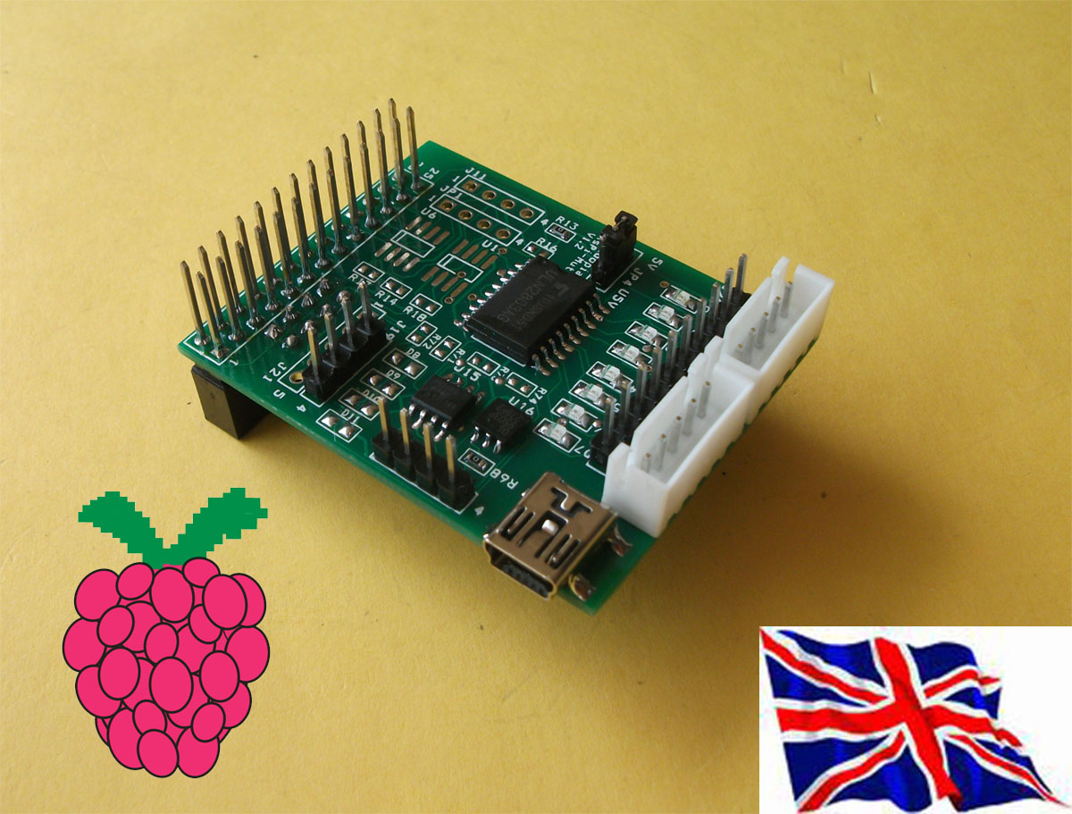
The 1-Wire port is based around a DS2482-100 I2C to 1-Wire bridge device. The DS2482-100 provides bi-directional protocol conversion between the I2C port on the Raspberry Pi and any attached 1-Wire® slave devices. An ESD Protection Diode is used to protect the Board and Raspberry Pi from electrostatic spikes on the 1-Wire port. Connections to the 1-Wire port can be made through pin on the PCB. 1. J2 J3 Step motor connector J2 (5V,D0,D1,D2,D3) J3(5V,D4,D5,D6,D7) can use Step motor (28BYJ-48 5VDC)48 5VDC)48 5VDC)48 5VDC)8 5VDC) 2. J20 5V,GND, D0, D1,D2,D3,D4,D5,D6,D7 OUTPUT 3. U5 ULN2803 8 darlington transistor array 4. J17 RS-Pi-V2 GPIO output 5. J19 i2c output (GND,5V,SDA,SCL) 6. JP4 choose 5V input from Mini USB Port J7 or RS-Pi 5V 7. J7 Mini USB 5V input 8. U6 MCP3002 SPI Interface 10 bit Analog-to-Digital Converter output J11 (Vcc, AD0, GND, AD1) MCP3002 Data Sheet 9. U11 MCP4802 SPI Interface 8 bit Digital-to-Analog Converter or U11 MCP4812 SPI Interface 10 bit Digital-to-Analog Converter or U11 MCP4822 SPI Interface 12 bit Digital-to-Analog Converter output JP1 (DA0,GND,DA1,GND) MCP4802 Data Sheet You can choose 8 bit , 10bit or 12 bit DAC , 10. U15 DS2482-100 I2C to 1-Wire bridge device DS2482-100 Data Sheet J22 1-wire Port pin 1 - pin4 (5V,GND, OW (1-Wire Data, ESD Protected). RT (1-Wire Return/Ground ,ESC protected) 11. U16 DS9503P ESD protection diode 12. D8,D9, D10, D11 GPIO 28,29,30.31 output LED U5 uln2803 use RS-Pi pin 11,12,13,15,16,18,22,7 as GPIO 0 to GPIO7 MCP3002 use 10k ohm Trimpot for INPUT DEMO |
MCP4802 OUTPUT DEMO You also can use gertboard program atod & dtoa in this board 18 -> DS2482-100 I2C 1-Wire bridge chip /28.7E1CC8030000 - Connect & Detect DALLAS 18B20P TEMP Sensor
28.7E1CC8030000 - Connect & Detect DALLAS 18B20P TEMP Sensor cat temperature -- 22.312 & 32.125
|
|