|
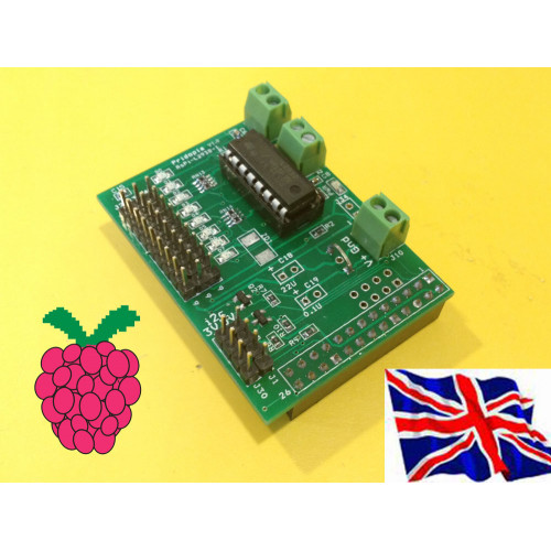
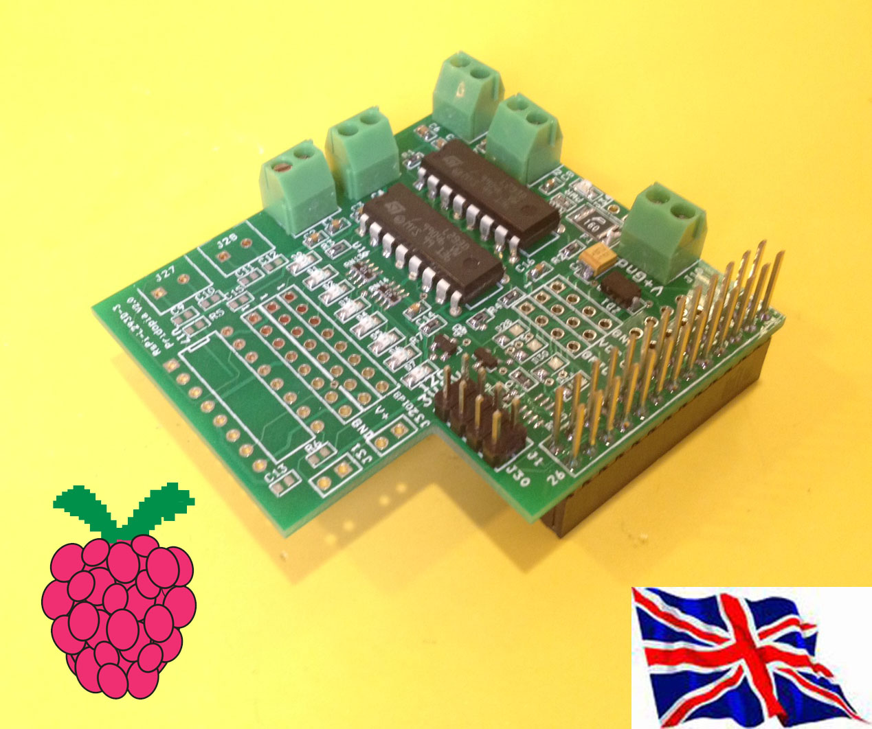
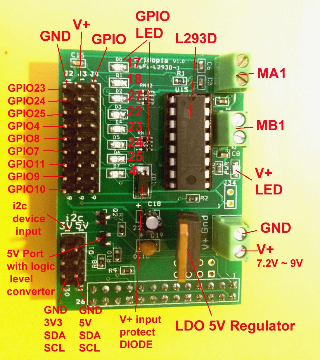
1. This board use RS-Pi GPIO 17,18,27,22 for two Motor GPIO 17,18 for MA1 GPIO 27,22 for MB1 2, GPIO 17,18,27,22,23,24,25,4 with status LED easy too know the GPIO high/low 3. GPIO 23,24,25,4,7,8,9,10,11 have GPIO pin for software PWM (Servo Motor) or sensors4. 2 i2c device input port J1 GND,5V,SDA,SCL 5V Port with Logic Level converter protect J30 GND, 3V3,SDA,SCLfor plug-in other sensors 5. Red LED for Power Status for Motor (V+ input) 6. 5V LDO regulator - input DC 7.2V to 9V output 5V Rs-Pi-L293d-1-pw plug in Raspberry Pi Full Support by our Pi_Scratch software can be very easy control by Scratch Pi_Scratch detail
(1) BASIC GPIO Motor control
|
BASIC GPIO Motor on off control define GPIO 17,18,27,22, as output 1. GPIO 17,27 LED "ON" & 18,22 LED "OFF" car move forward 2. GPIO 18,22 LED "ON" & 17,27 LED "OFF" car move backward 3. GPIO 18,27 LED "ON" & 17,22 LED "OFF" car turn right 4. GPIO 17,22 LED "ON" & 18,27 LED "OFF" car turn left 5. GPIO 17,27 LED "OFF" & 18,22 LED "OFF" car STOP (2) PWM GPIO Motor control
A - GPIO 17,18 Motor A B - GPIO 27,22 Motor B command "Motor Name"+ "DM"+"speed" speed (10 ~100) clockwise speed (-10 ~ -100) anticlockwise ADM100 DC Motor A full speed 100 BDM100 DC Motor B full speed 100 ADM50 DC Motor A speed 50 BDM50 DC Motor B speed 50 ADM-100 DC Motor A anticlockwise full speed 100 BDM-100 DC Motor B anticlockwise full speed 100 ADM0 DC Motor A stop BDM0 DC Motor B stop
|