|
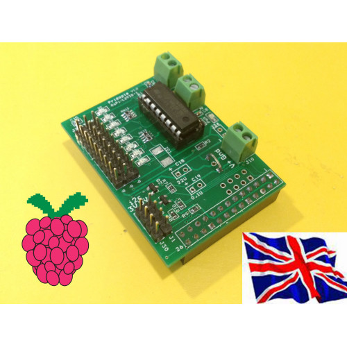
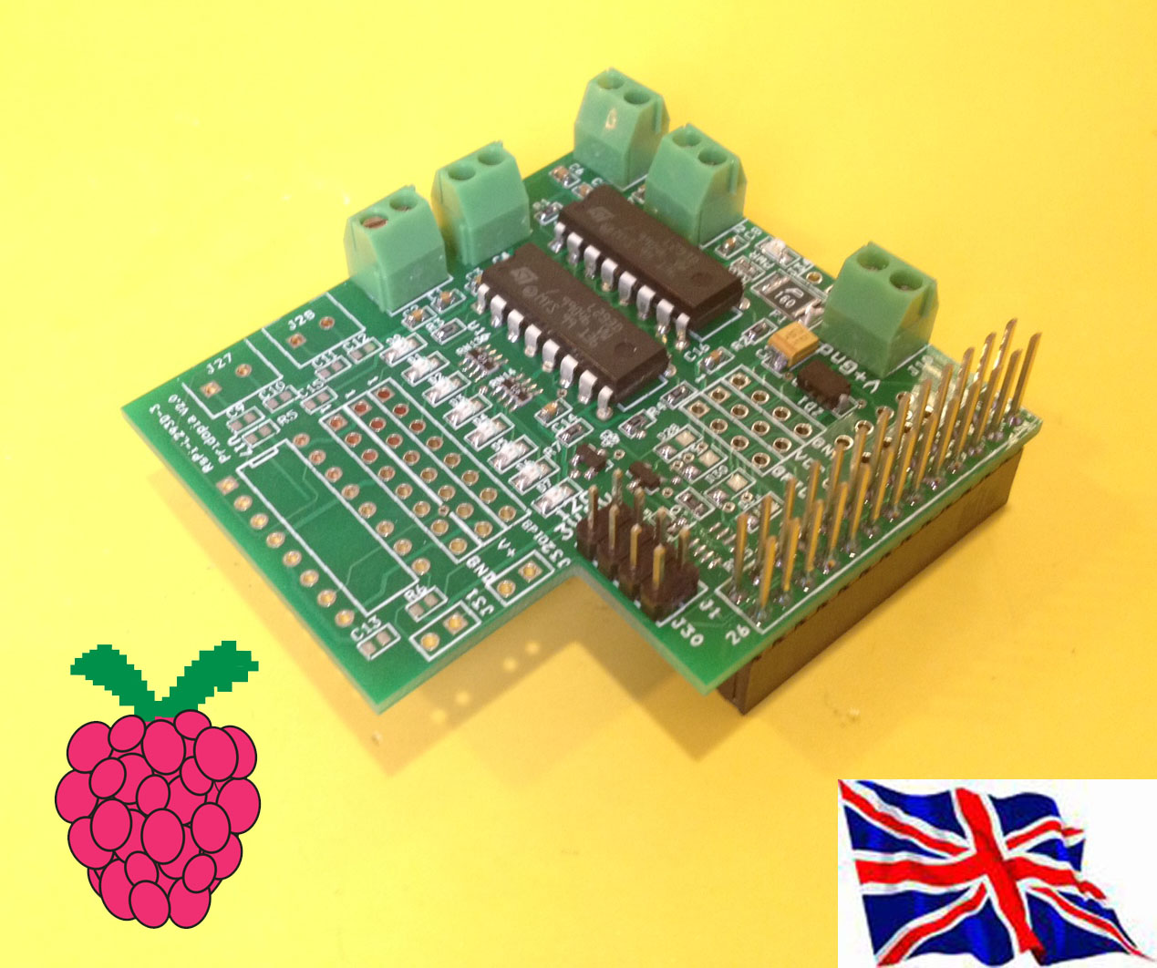
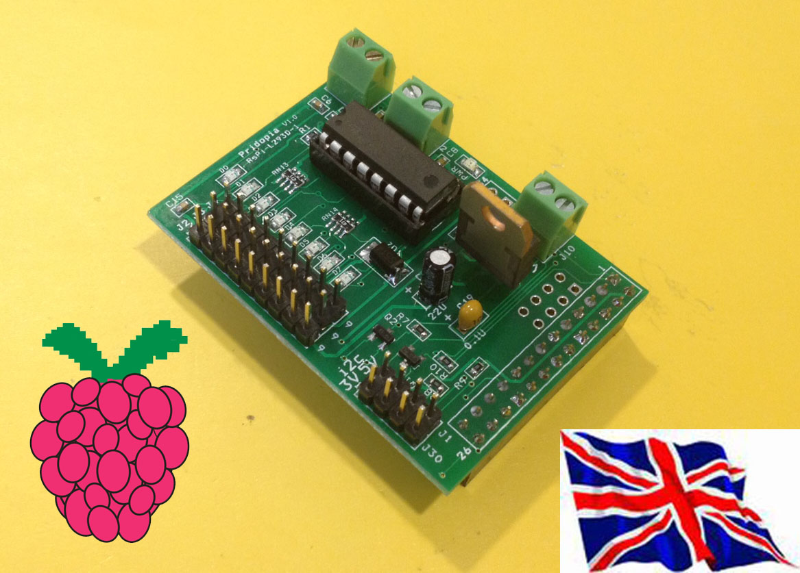
1. J2 J3 Step motor connector J2 (5V,D0,D1,D2,D3) J3(5V,D4,D5,D6,D7) can use Step motor (28BYJ-48 5VDC)48 5VDC)48 5VDC)48 5VDC)8 5VDC) 2. J20 5V,GND, D0, D1,D2,D3,D4,D5,D6,D7 OUTPUT 3. U5 ULN2803 8 darlington transistor array 4. J17 RS-Pi-V2 GPIO output 5. J8 i2c output (GND, 3V3, SDA,SCL) 6. J19 i2c output (GND,5V,SDA,SCL) 7. JP4 choose 5V input from Mini USB Port J7 or RS-Pi 5V 8. J7 Mini USB 5V input 9. U6 MCP3002 SPI Interface 10 bit Analog-to-Digital Converter output J11 (Vcc, AD0, GND, AD1) 10. U11 MCP4802 SPI Interface 8 bit Digital-to-Analog Converter output JP1 (DA0,GND,DA1,GND)
U5 2803 use RS-Pi pin 11,12,13,15,16,18,22,7 as GPIO 0 to GPIO7
MCP3002 use 10k ohm Trimpot for INPUT DEMO |
MCP4802 OUTPUT DEMO
You also can use gertboard program atod & dtoa in this board
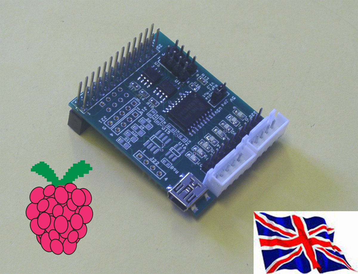
Can work with our RS-Pi-USB Hub Board & I2C 23017 Board |