
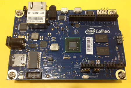
Galileo is a microcontroller board based on the Intel® Quark SoC X1000 Application
Processor, a 32-bit Intel Pentium®-class system on a chip (SoC). It is the first board
based on Intel® architecture designed to be hardware and software pin-compatible
with shields designed for the Arduino Uno R3.
This platform provides the ease of Intel architecture development through support for
the Microsoft Windows*, Mac OS* and Linux* host operating systems. It also brings
the simplicity of the Arduino software integrated development environment (IDE).
The Galileo board is also software-compatible with the Arduino Software Development
Environment, which makes usability and introduction a snap. In addition to Arduino
hardware and software compatibility, the Galileo board has several PC industry
standard I/O ports and features to expand native usage and capabilities beyond the
Arduino shield ecosystem. A full sized mini-PCI Express slot, 100Mb Ethernet port,
Micro-SD slot, RS-232 serial port, USB Host port, USB Client Port, and 8 MByte NOR flash come standard on the board.
The genuine Intel processor and surrounding native I/O capabilities of the SoC provides
for a fully featured offering for both the maker community and students alike. It will also
be useful to professional developers who are looking for a simple and cost effective
development environment to the more complex Intel® Atom™ processor and Intel®
Core™ processor-based designs.
The default Linux Image in Micro SD card
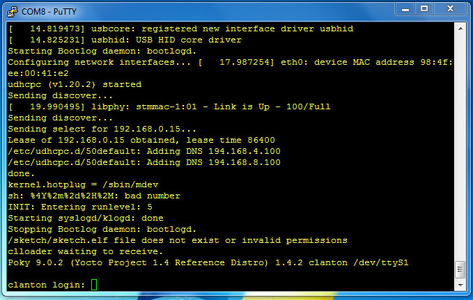
use RS232 console port login
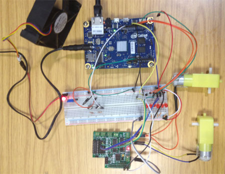
use our Pi-L293D-3 control 2 Motor, also 2 switch input test,
GPIO input
GPIO output
Analog input
PWM Motor Speed control
We provide a simple GPIO control library, to make easy control GPIO pin.
Version
GPIO_intel_v10 -- V1.0 28,Feb 2014 GPIO_intel_v101 -- V1.01 05,Mar 2014
Download GPIO_intel Software tar format v1.01
or use the following command from your Galileo
wget http://pridopia.co.uk/ga-pgm/GPIO_Intel_v101.tar
or wget http://pridopia.com/ga-pgm/GPIO_Intel_v101.tar
tar xf GPIO_Intel_v101.tar
cd GPIO_Intel_v101
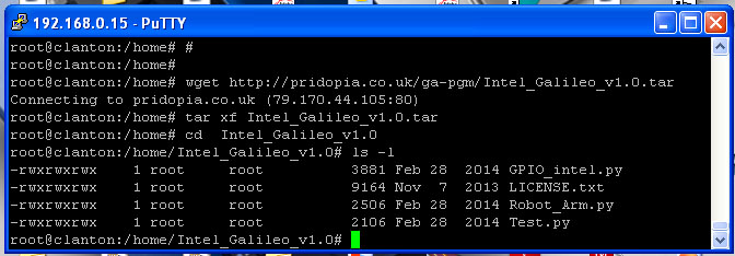
have 1 library file GPIO_Intel.py
three python example files Test.py , Robot_Arm.py, Step.py
one License document LICENSE.txt
If you have any suggestions or requirement please send an email to

detail as below
python test program
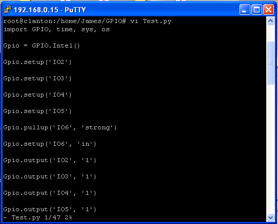
To import the module you need to type
>> import Intel_Gpio
to start / initialize the script you need to run the __init__ function and assign it to a Variable / Object.
>> GPIO = Intel_Gpio.Intel()
Now you can start to Output, Input, Setup, PWM Pins. The naming layout is as follows;
For IO Pins from 2 through to 13 the names start with IO and are followed with the Pin number on
the board. e.g. IO2
For Analogue pins, It is the same as IO Pins but starts with A e.g. A2
For PWM Pins, the command starts with PWM and followed with the number on the board e.g.
PWM3, PWM5, PWM6.
To output to a Pin you need to set up the Pin.
>> GPIO.setup('IO2') ( This will set IO2 to output by Default )
The next thing you need to do is output a number ( 1 / 0 )
>> GPIO.output('IO2', 1) ( This will output 1 to IO2 Pin )
To set a Pin as an Input you will need to setup the pin as input by doing
>> GPIO.setup('IO2', 'in') ( setup can either be 'in' or 'out' )
Then you can call input() to get the pin value.
>> print GPIO.input('IO2')
This will print out the current value of IO2,
To set a PWM channel you need to type the following;
>> GPIO.pwm('PWM3', duty='0.1') ( The Duty is how long the signal is up for. The default period
length of the signal is 2ms which is 0.2, So a duty_cycle of 0.1 would be half on, half off )
You can change the Period, The number 0.2 is default and is 2 million nanoseconds or 2
milliseconds
>> GPIO.pwm('PWM3', period='2000000', duty='1000000')
That is the default command if you just type in GPIO.pwm('PWM3')
To stop a PWM signal or to use normal GPIO again on that pin, type the command;
>> GPIO.pwm_shutdown('PWM3')
That will disable the PWM and you can return to normal IO Control.
(1) Example 1
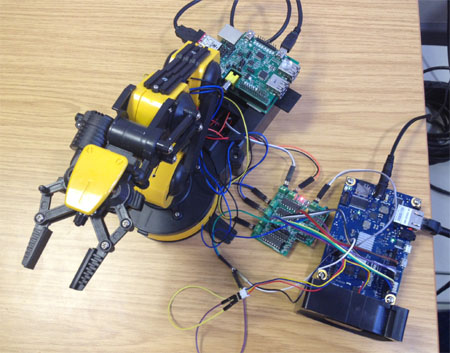
Galileo control 5 motor Robot Arm
Use 1.Rs-pi–L293D-3 6 Motor Board -
Control Robot Arm 5 Motor (M1,M2,M3,M4,M5)
KEYBOARD A,B M5 C,D M4 E,F M3
G,H M2 I,J M1

(2) Example 2
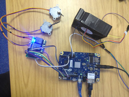
use our Rs- Pi 2803 2 Relay - Step Motor Board & 2 28byj48 5V step Motor


0 Comment